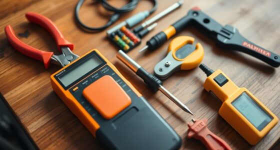

To use a multimeter for DIY electrical tests, start by understanding its main parts: the probes, rotary switch, and display. Always set the dial to the correct function and range before testing. For voltage, connect the probes across the circuit; for current, place them in series after turning off power. To check resistance or continuity, disconnect power and connect probes across the component. Following proper safety steps guarantees accurate results—keep reading to learn more tips.
Key Takeaways
- Always turn off power and disconnect circuits before measuring resistance or continuity to ensure safety and accuracy.
- Select the correct measurement mode (voltage, current, resistance) and range on the rotary switch before testing.
- Connect probes properly: black in COM first, red in VΩmA or 10A terminal depending on measurement type.
- For current tests, break the circuit and connect the multimeter in series; start with the highest range to prevent damage.
- Use proper safety practices, handle probes carefully, and verify multimeter ratings for mains voltage testing.
Understanding the Main Components of a Multimeter
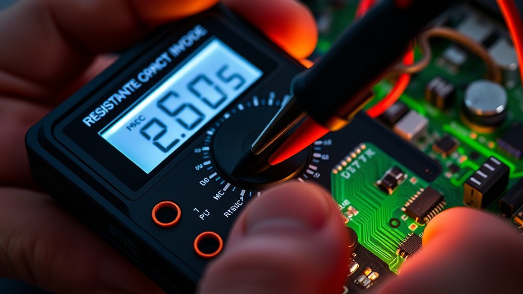
Understanding the main components of a multimeter is essential for using it safely and effectively. Your multimeter has three key terminals: COM (common or ground), VΩmA (for voltage, resistance, and small current), and 10A (for measuring larger currents up to 10 amps). The black probe always connects to COM, while the red probe goes into the appropriate terminal depending on your measurement. The rotary switch selects the function—voltage, resistance, or current—and adjusts the range for accuracy. The display shows the measurement value and may display indicators like “OL” for overload or open circuits. Knowing these components helps you set up correctly, choose the right measurement mode, and protect yourself and your device during testing. Additionally, understanding multimeter safety practices is also crucial to prevent accidents or damage during testing. Being familiar with the range selection ensures accurate readings and avoids damaging your multimeter or the circuit being tested. Properly understanding the circuit behavior can help you troubleshoot electrical issues more effectively and safely. Recognizing how different measurement modes interact with various circuit components can further improve your testing accuracy.
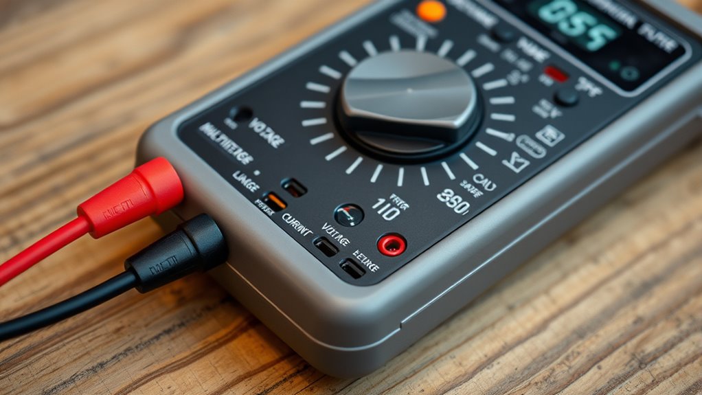
Setting Up Your Multimeter Safely and Correctly

To set up your multimeter safely, start by placing the probes correctly—black in COM and red in the appropriate terminal for your measurement. Always select the right measurement mode on the dial before testing, whether it’s voltage, resistance, or current. Remember to turn off power to the circuit before connecting your multimeter to avoid damage or injury. Additionally, choosing energy-efficient and secure measurement techniques helps protect both the user and the device, aligning with European cloud innovation standards. Proper safety procedures ensure accurate results and prevent accidents during electrical testing. Familiarizing yourself with multimeter calibration can further enhance measurement accuracy and safety. Being aware of electrical safety protocols is essential for safe and effective testing. Understanding measurement best practices can also help improve the reliability of your results and prevent mishaps.
Proper Probe Placement
Proper probe placement is essential for safe and accurate multimeter measurements. You should always insert the black probe into the COM terminal first, as it serves as the common ground. The red probe goes into the appropriate terminal based on what you’re measuring—VΩmA for voltage, resistance, or small current, and 10A for high current tests. When measuring voltage or resistance, place the probes directly across the component or circuit points, ensuring firm contact. For current measurements, break the circuit and connect the probes in series, with the red probe in the current path. Keep your fingers behind the finger guards on the probes to avoid accidental contact. Proper placement minimizes errors and protects you from potential electric shocks. Additionally, understanding the proper use of the multimeter helps prevent damage to the device and ensures reliable readings. Being aware of safe testing practices is crucial when working with electrical systems to avoid hazards. It is also helpful to familiarize yourself with the different measurement modes to select the correct settings for each test.
Selecting Correct Measurement Mode
Choosing the correct measurement mode on your multimeter is essential for safe and accurate current testing. First, turn the dial to the current (A) setting, selecting either milliamps (mA) or amperes (A) based on expected current levels. For small currents, start with the 200mA or 10A range, which protects your meter from overload. Always use the appropriate port: red probe into the 10A terminal for high currents, or VΩmA port for lower currents. Never measure current in voltage mode, as it can damage the meter or cause injury. Confirm the circuit is properly set up in series with the multimeter, and double-check the range before connecting. Correct mode selection guarantees safety and reliable readings for your DIY electrical tests.
Ensuring Circuit Power Off
Before connecting your multimeter to measure current, always verify the circuit is powered off. This step is vital to prevent damage to your meter and guarantee safety. To do this effectively:
- Turn off the power supply or unplug the device.
- Confirm the circuit is de-energized with a voltage test, if necessary.
- Discharge any stored energy in capacitors or components.
- Use insulated tools to handle connections safely.
How to Measure Voltage in Various Circuits

Measuring voltage in various circuits is a fundamental step in troubleshooting and diagnostics, and it requires selecting the correct settings and safety precautions. First, set your multimeter to AC or DC voltage depending on the source. Always start with the highest range to prevent overload, then lower it for more precise readings. Connect the black probe to the COM terminal and the red probe to the VΩmA terminal. For AC voltage, place the probes across the circuit or outlet, ensuring safety by keeping hands away from live parts. For DC voltage, disconnect power if necessary, then measure between positive and negative terminals. Read the voltage value on the display, verifying that it matches expected levels. Always disconnect probes before moving or adjusting your setup to maintain safety. Additionally, understanding the different types of circuits can help you select the appropriate measurement technique and ensure accurate readings.
Techniques for Measuring Electrical Current
To measure current accurately, you need to connect your multimeter properly within the circuit, ensuring it’s in series with the load. Always select the correct range before taking a reading to prevent damage and get precise results. Starting with a higher range and adjusting downward helps protect the meter and improves accuracy. Additionally, understanding the best heat pump features can help ensure the electrical system is compatible and operating efficiently. Being familiar with the multimeter safety precautions can also prevent accidents and ensure accurate measurements. It’s also helpful to familiarize yourself with the support breakfast options to understand how different features can enhance your overall setup. For optimal safety and performance, regularly calibrating your multimeter according to industry standards is recommended. Proper circuit testing techniques further ensure that your readings are reliable and safe.
Proper Circuit Connection
Ensuring a proper circuit connection is essential when measuring electrical current, as it guarantees accurate readings and prevents damage to your multimeter. To do this effectively, follow these steps:
- Turn off power before connecting to avoid shorts or shocks.
- Break the circuit at the point where you want to measure current.
- Insert the black probe into COM and the red probe into the 10A or mA port, depending on the current.
- Place the probes in series with the circuit, ensuring contact across the break.
- Understanding circuit flow helps you determine the best point to measure current safely and accurately.
- Regularly verify that your multimeter is functioning properly to ensure reliable measurements, especially when working with electrical systems.
Make sure the multimeter is set to the correct current range before measuring. Never measure current without breaking the circuit first, as this could damage your device or cause injury. Proper connection is key for safe, accurate testing.
Selecting Correct Range
When measuring current, selecting the correct range on your multimeter is essential for obtaining accurate readings and protecting your device. Start with the highest current range available, such as 10A, to prevent damage if you’re unsure of the circuit’s current. Then, gradually lower the range to improve accuracy once you get a rough estimate. Always ensure the red probe is in the correct port—either the 10A or mA terminal—before measuring. If the display shows “OL” or overload, move to a higher range. Conversely, if the reading is very low and stable, switch to a lower range for more precise results. Proper range selection minimizes the risk of blowing internal fuses and guarantees your measurements are safe and accurate.
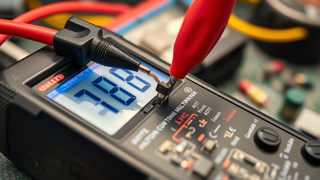
Testing Resistance and Continuity in Circuits
Testing resistance and continuity in circuits is a fundamental step in diagnosing electrical issues. It helps you identify open circuits, broken wires, or faulty components. To get accurate results:
- Disconnect power and ensure the circuit is unpowered before testing resistance or continuity.
- Set your multimeter to the resistance (Ω) or continuity mode.
- Connect the probes across the component or wire; a steady beep indicates continuity.
- A reading of ‘0’ ohms shows a good connection, while infinite resistance signals a break.
Remember to start with the highest resistance or continuity range and adjust downward for precision. Always handle probes carefully, and double-check connections before testing to prevent false readings or damage. This process helps you quickly locate faults without damaging your multimeter.
Diagnosing Components: Diodes, LEDs, and Fuses
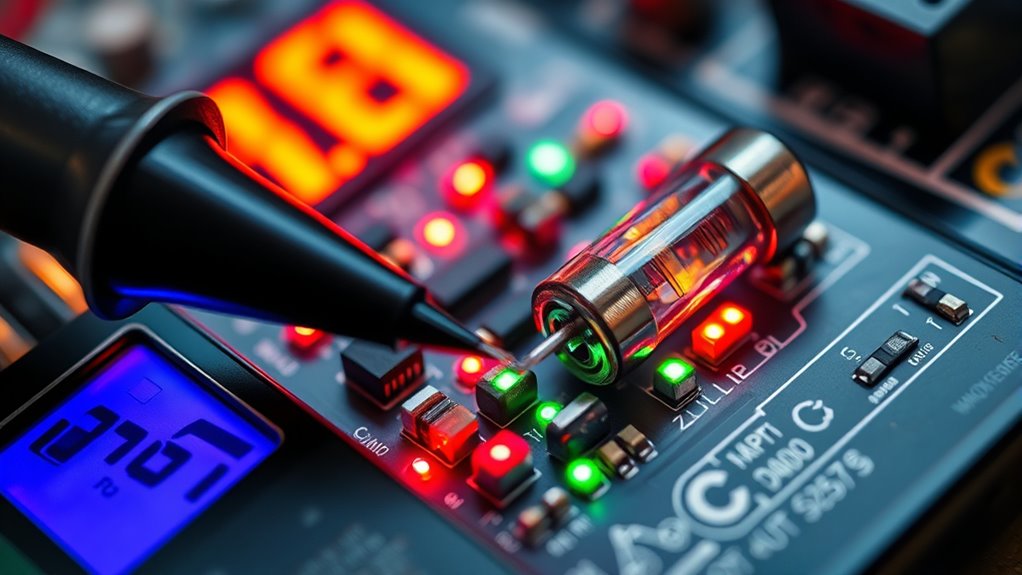
Diagnosing diodes, LEDs, and fuses with a multimeter involves specific testing procedures to verify their functionality. To test a diode or LED, set your multimeter to the diode test mode (symbol resembling a diode arrow). Place the probes across the component’s leads; a good diode or LED will show a forward voltage around 0.6 to 0.7 volts, and the LED may glow faintly. Reversing the probes should result in an OL (overload) reading, indicating no current flow. For fuses, switch to resistance mode; a functioning fuse will show close to 0 ohms, while a blown fuse reads as infinite resistance. Always disconnect components from power before testing to prevent damage and guarantee safety. Proper testing confirms if these components are operational or need replacement.
Practical Tips for Safe and Accurate Testing

To guarantee accurate results and stay safe during multimeter use, it’s important to follow best practices consistently. First, always disconnect power before measuring resistance or continuity to prevent damage or injury. Second, start with the highest measurement range and adjust downward for precision, protecting your device. Third, handle probes carefully—insert black first, remove red last—to reduce shock risk. Fourth, verify your multimeter’s ratings—use Category II or higher for mains voltage tests—to assure safety. Additionally, keep your hands steady and avoid touching metal parts during testing. Proper probe placement and correct terminal use are vital. By following these tips, you’ll improve accuracy and minimize hazards while working on electrical projects.
Common Mistakes to Avoid When Using a Multimeter
One common mistake is measuring current without disconnecting the circuit first. You might connect the multimeter in series without turning off power or opening the circuit, risking damage to the meter and circuit. Always turn off power and disconnect the circuit before switching the multimeter to current mode. Make sure you insert the red probe into the correct port—either mA or 10A—depending on the expected current. Using the wrong port or range can blow internal fuses or damage the device. Also, avoid measuring current on a live circuit without proper setup, as it can lead to inaccurate readings or accidents. Always verify your connections and settings before taking a measurement to ensure safety and accuracy.
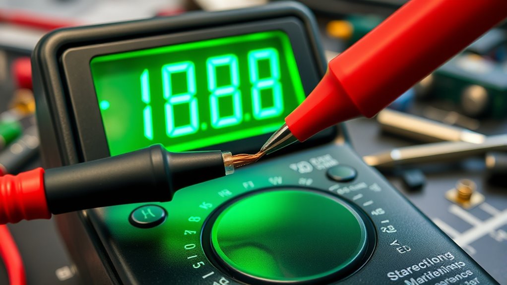
Interpreting Multimeter Readings for Troubleshooting

Understanding multimeter readings is essential for pinpointing electrical issues effectively. When you interpret readings correctly, troubleshooting becomes faster and more accurate. Here are four key points to help you analyze measurements confidently:
- Voltage readings: A healthy circuit shows expected voltage levels; markedly low or no voltage indicates a power supply problem.
- Current measurements: Excessively high current suggests a short or overload, while very low current may point to an open circuit or faulty component.
- Resistance values: Zero ohms indicates a good connection; infinite resistance signals a broken wire or blown fuse.
- Continuity tests: A beep confirms a complete circuit; no sound means an open circuit needing repair.
Mastering these interpretations allows you to diagnose issues efficiently and safely.
Frequently Asked Questions
Can I Use a Multimeter to Test Live Circuits Safely?
You can use a multimeter to test live circuits, but you must do so carefully. Always set the multimeter to the correct voltage range for AC or DC, and make certain you’re using a multimeter rated for high voltage, like Category II or higher. Keep your hands steady, avoid touching metal parts, and follow safety guidelines. Disconnect power before measuring resistance or continuity to prevent damage or injury.
What Is the Difference Between AC and DC Voltage Measurements?
Think of AC voltage like ocean waves, constantly changing, while DC voltage is like a steady river flow. You measure AC to check mains power or outlets, where voltage fluctuates, and DC for batteries or solar panels, which provide a constant voltage. When measuring AC, you’re capturing the oscillating voltage; for DC, you’re reading a stable, unidirectional flow. Always set your multimeter correctly to avoid inaccurate readings or damage.
How Do I Choose the Correct Current Range for Testing?
You choose the correct current range by starting at the highest setting, usually 200mA or 10A, to prevent damage. Then, gradually switch to lower ranges for more precise readings. Always match the range to the expected current; if unsure, start high and adjust downward. Remember to place the probes correctly and make sure the circuit is broken to insert the meter in series safely.
Why Does My Multimeter Display “Ol” During Testing?
You see “OL” on your multimeter because the measurement exceeds the selected range or the circuit is open. To fix this, switch to a higher range to handle the voltage or current, or check for an open circuit. Make sure your probes are connected correctly, and the circuit is powered properly. Always verify your range settings before testing to prevent overload readings like “OL.”
How Do I Test for Broken or Damaged Wires Using a Multimeter?
Imagine chasing a silent whisper in a tangled web—your wires. To test for broken or damaged wires, set your multimeter to continuity mode. Place the probes at each end of the wire. If you hear a beep, the connection’s intact; if not, the wire’s broken or damaged. Remember, disconnect power first. This simple test reveals hidden faults, restoring harmony to your electrical symphony.
Conclusion
Now that you know the basics, you’re ready to tackle electrical tests with confidence. But remember, every measurement reveals more than you might expect—hidden faults, subtle signals, or unexpected quirks. Will your next test uncover a simple glitch or a more serious issue? Stay attentive, follow safety tips, and trust your skills. Because in the world of DIY electronics, the next surprising discovery could be just one measurement away.